 Developers
 Components
 Openflexo-core
 Technology-Adapters
 Openflexo Modules
Tutorial 7 : Working on model mapping
1. Purpose of this tutorial
Model federation is a powerfull paradigm to modelize and implement model mapping (etablishing mappings between two partially aligned models).
In this tutorial, you will learn how to define and execute model mapping between two partially aligned models. Some some reasons, both models are homogeneous relatively to their technical space (EMF technology), but we can do the same with heterogeneous technologies.
The general issues addressed by this tutorial are the following:
- Install and use of an existing ViewPoint in a ViewPoint Modeller
- Browsing of a ViewPoint using Openflexo ViewPoint Modeller
- Defining a model mapping between two meta-models
- Operationalizing (including generation and synchronizing) a model mapping between two meta-models
- Instanciation and use of a model mapping ViewPoint in the ViewEditor
2. Context
The “CityMapping” prototype was build to demonstrate the model mapping facilities over heteregenous models, in the context of model federation. Suppose we have here two metamodels encoded in EMF (ECore) technology. Those two models are mostly aligned, but with some notions which are to be explicitly mapped. Following figure shows the both metamodels (metamodel1 in blue, and metamodel2 in red).
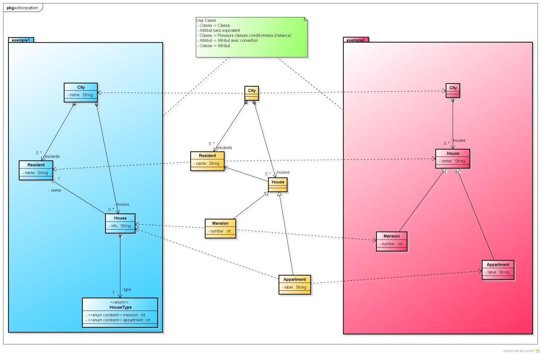
Following mapping patterns occur:
- In metamodel1, one instance of City class maps one instance of City class in metamodel2
- In metamodel1, an attribute of class House (type of enum HouseType) encodes the type of house (apartment or mansion), while in metamodel2, an inheritance pattern declares two subclasses Appartment and Mansion inheriting from House class. One instance of House in metamodel1 maps one instance of Appartment or Mansion in metamodel2, depending on the value of type attribute in metamodel1
- In the HouseAppartment mapping, info attribute of House instance in metamodel1 maps label attribute of Appartment instance in metamodel2
- In the HouseMansion mapping, info attribute of House instance in metamodel1 maps number attribute (its String representation) of Mansion instance in metamodel2
- In metamodel1, one instance of Resident class maps the property value owner of one instance of House in metamodel2 (ClassProperty mapping)
Note that this “toy” use case has been built from real industrial use cases (trying to generalize mapping patterns). From a conceptual point of view, we see that a mapping between those two partially aligned models might be considered. Some mapping options for ambiguous data should be also clearly considered, as well as the necessity for a real human to take some mapping decisions. From an operational point of view, many use cases should be also considered:
- We have the two existing models, and we ask the computer to automatically compute the mapping
- We have the two existing models, and we ask the computer to automatically compute the mapping. Some mappings are ambiguous and should be solved by a user decision.
- We have the two existing models, and the mapping is automatically computed. The user decides to synchronize one model from the other one, or the inverse, or to merge the two models (in case of some instances of one model are not present in the other one).
- We have only one of the two models. The other model should be fully generated from existing models.
- We have no models. Both models should be created from scratch, and an editor should provide features to edit both synchronized models according to the defined mapping.
- …
In this tutorial, we will see how Openflexo software might offer some solutions for those issues (from both conceptual and operational point of view).
3. Launch tutorial project
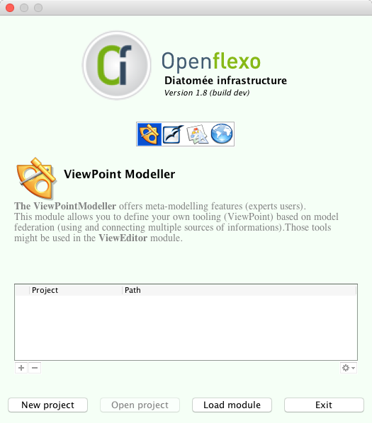
3.1 Install Openflexo
As a preliminary phase, you should get a recent Openflexo distribution (Openflexo Maintainer 1.8.x recommanded)
Download it on:
- https://developers.openflexo.org/developers/download.html
- Alternatively take the current 1.8.x snapshot (https://downloads.openflexo.org/openflexo/1.8.0SNAPSHOT/)
3.2 Download tutorial project
Download the tutorial project (Tutorial7.prj) on github (project integration-tests-rc)
Alternative .zip file might be found here:
https://developers.openflexo.org/images/tutorials/Tutorial7-WorkingOnModelMapping/Tutorial7.prj.zip
4. Browse CityMapping ViewPoint, conceptually defining model mapping
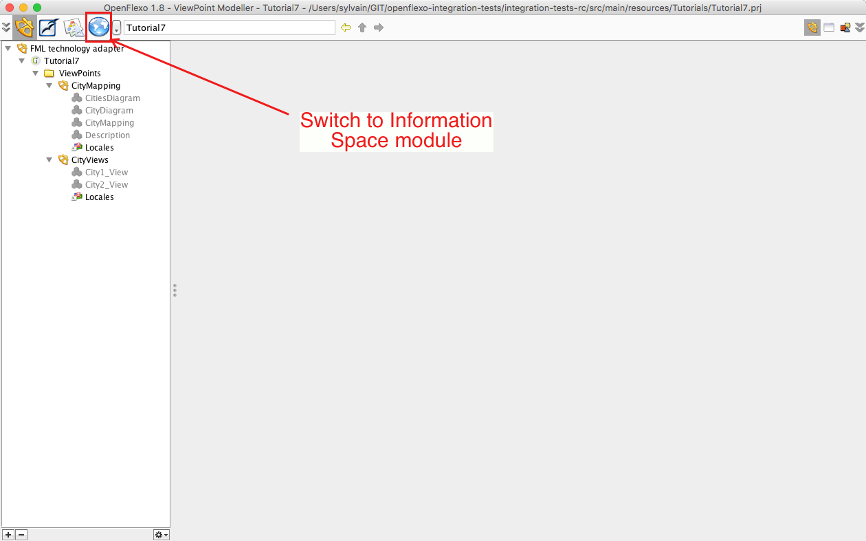
4.1 Browse Information Space
Switch to Information Space Module.
The purpose of that module is to provide browing and editing facilities to technology-specific resources.
We aim here at having a look to two EMF metamodels:
- city1: which corresponds to the blue EMF metamodel
- city2: which corresponds to the red EMF metamodel
Activate EMF TechnologyAdapter and switch to EMF perspective.
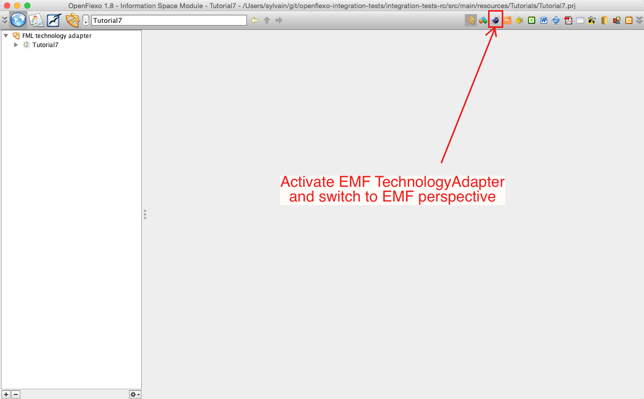
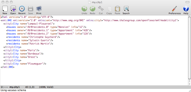
Each technology adapter can provide a perspective service that allows to browse corresponding resources. A technology adapter allows Openflexo to interpret (read/write/edit) data informations encoded with a specific technology. In EMF technology adapter perspective Openflexo shows various EMF modelling elements. Here we see the 3 EMF metamodels contained in the project, and some models conformed to those metamodels (also present in the project). Double-clicking for example on the city1 metamodel opens an editor editing corresponding metamodel:

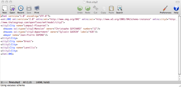
Please note that this metamodel is the one presented in first diagram (blue metamodel, see section 2). Double-clicking for example on the city2 metamodel opens an editor editing corresponding metamodel:
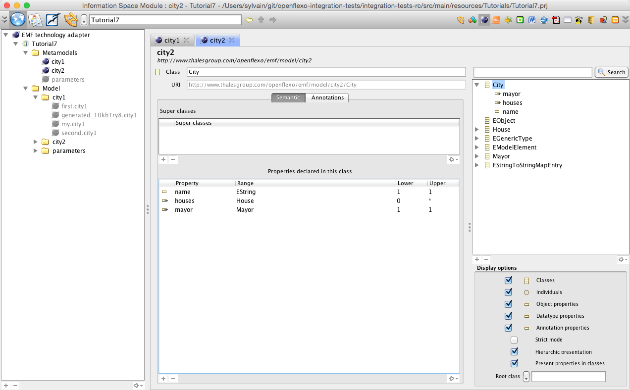
Please note that this metamodel is the one presented in first diagram (red metamodel, see section 1). You might notice here that in second metamodel, House is subclassed with Appartment and Mansion, while in first metamodel House has an enum attribute encoding the type of the house.
4.2 Browse ViewPoint
Switch back to ViewPointModeller.
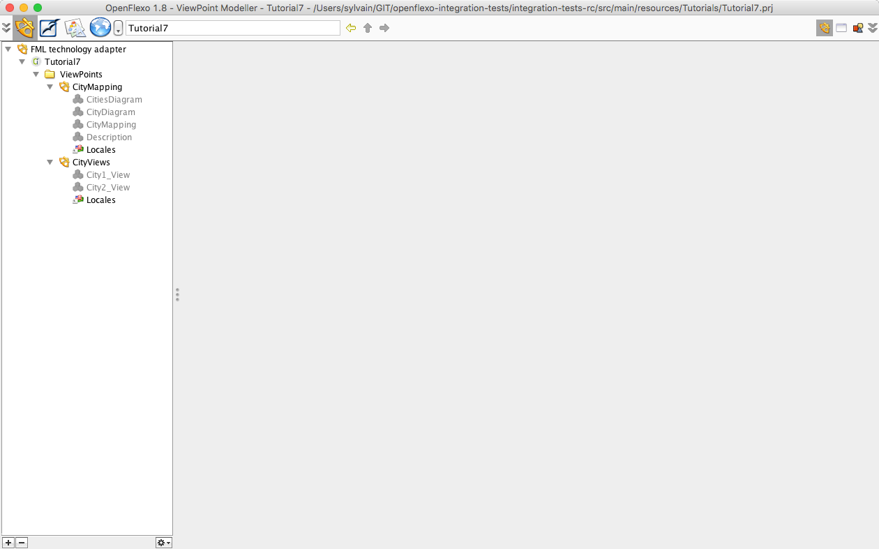
4.2.1 Overview
Select and double-click on CityMapping ViewPoint. The ViewPoint loads. Select and double-click on CityMapping virtual model.
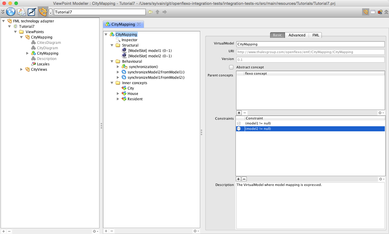
This VirtualModel will conceptually define the mapping between the both models. To do this, we have defined here two model slots (symbolic links to real models, which must be resolved at run-time):
- Model slot _‘model1_’ : defines the reference to an EMF model called model1, conform to city1 metamodel
- Model slot _‘model2_’ : defines the reference to an EMF model called model2, conform to city2 metamodel
4.2.2 Federated concepts
As shown in introductory diagram, we will define inside this VirtualModel some ’federated concepts’, which implement the mapping between some modelling elements encoded in technical space. Those federated concepts are purely virtual, and depend of the context (here the problematic of model mapping between two known EMF metamodels). In Openflexo, those federated concepts are called _‘FlexoConcepts_’. Those federated concepts are defined as:
- City
- House which is specialized into Appartment and Mansion
- Resident
4.2.3 Federated concept City
Select and double-click on City FlexoConcept.
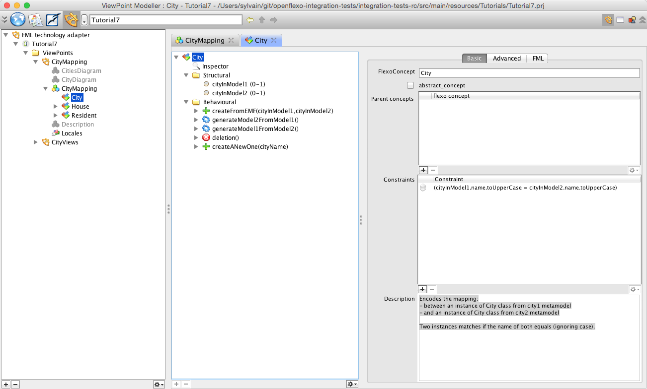
Remember that in metamodel1, one instance of City class maps one instance of City class in metamodel2. To conceptualize this, we have defined an FlexoConcept City, with two flexo roles:
- cityInModel1: references an instance of City class in metamodel city1
- cityInModel2: references an instance of City class in metamodel city2
(Note that we have two different City classes) We need to specify a conditional mapping rule: names of cities should match (ignoring case). To do so, we need to define a constraint as a conditional expression:cityInModel1.name.toUpperCase = cityInModel2.name.toUpperCase To see it, open the inspector (CTRL-I or Windows>Inspector), then select the City FlexoConcept.
4.2.4 Federated concept Appartment
Select and double-click on Appartment FlexoConcept.
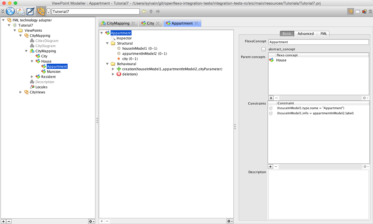
In metamodel1, an attribute of class House (type of enum HouseType) encodes the type of house (apartment or mansion), while in metamodel2, an inheritance pattern declares two subclasses Appartment and Mansion inheriting from House class. One instance of House in metamodel1 maps one instance of Appartment or House in metamodel2, depending on the value of type attribute in metamodel1 In the HouseAppartment mapping, info attribute of House instance in metamodel1 maps label attribute of Appartment instance in metamodel2 To conceptualize this, we have defined a FlexoConcept Appartment, with three flexo roles:
- houseInModel1: references an instance of House class in metamodel city1
- appartmentInModel2: references an instance of Appartment class in metamodel city2
- city: references to the City instance in this virtual model (the city where this appartment exists: containment relationship)
We need to specify a conditional mapping rule: type of house should be of type ‘Appartment’ To do so, we need to define a constraint as a conditional expression:houseInModel1.type.name = “Appartment” We need to specify an other conditional mapping rule: info value of House instance should be equals to label value of Appartment instance To do so, we need to define a constraint as a conditional expression:houseInModel1.info = appartmentInModel2.label To see it, open the inspector (CTRL-I or Windows>Inspector), then select the Appartment FlexoConcept. Then also need to reference the instance of FlexoConcept City where this Appartment is defined (the city where this appartment exists: containment relationship).
4.2.5 Federated concept Mansion
Select and double-click on Mansion FlexoConcept.
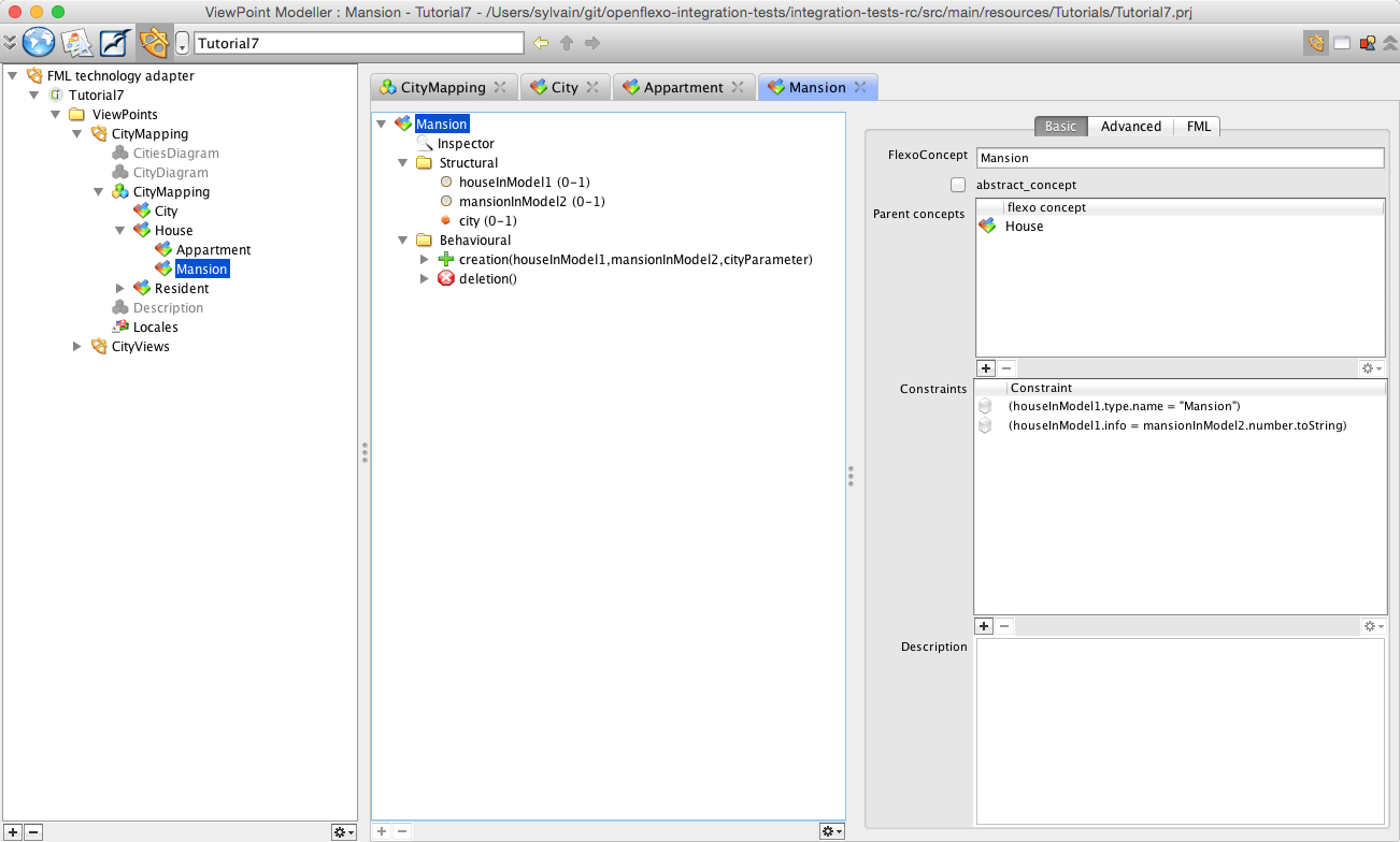
Following same logic as previously explained, in the HouseMansion mapping, info attribute of House instance in metamodel1 maps number attribute (its String representation) of Mansion instance in metamodel2. To conceptualize this, we then have defined a FlexoConcept Mansion, with three flexo roles:
- houseInModel1: references an instance of House class in metamodel city1
- mansionInModel2: references an instance of Mansion class in metamodel city2
- city: reference to the City instance in this virtual model (the city where this appartment exists: containment relationship)
We need then to specify a conditional mapping rule: type of house should be of type ‘Mansion’ We need to specify an other conditional mapping rule: info value of House instance should equals number value of Mansion instance. To do so, we need to define following constraints:houseInModel1.type.name = “Mansion”houseInModel1.info = mansionInModel2.number.toString Then also need to reference the instance of FlexoConcept City where this Mansion is defined (the city where this appartment exists: containment relationship).
4.2.6 Federated concept Resident
Select and double-click on Resident FlexoConcept.
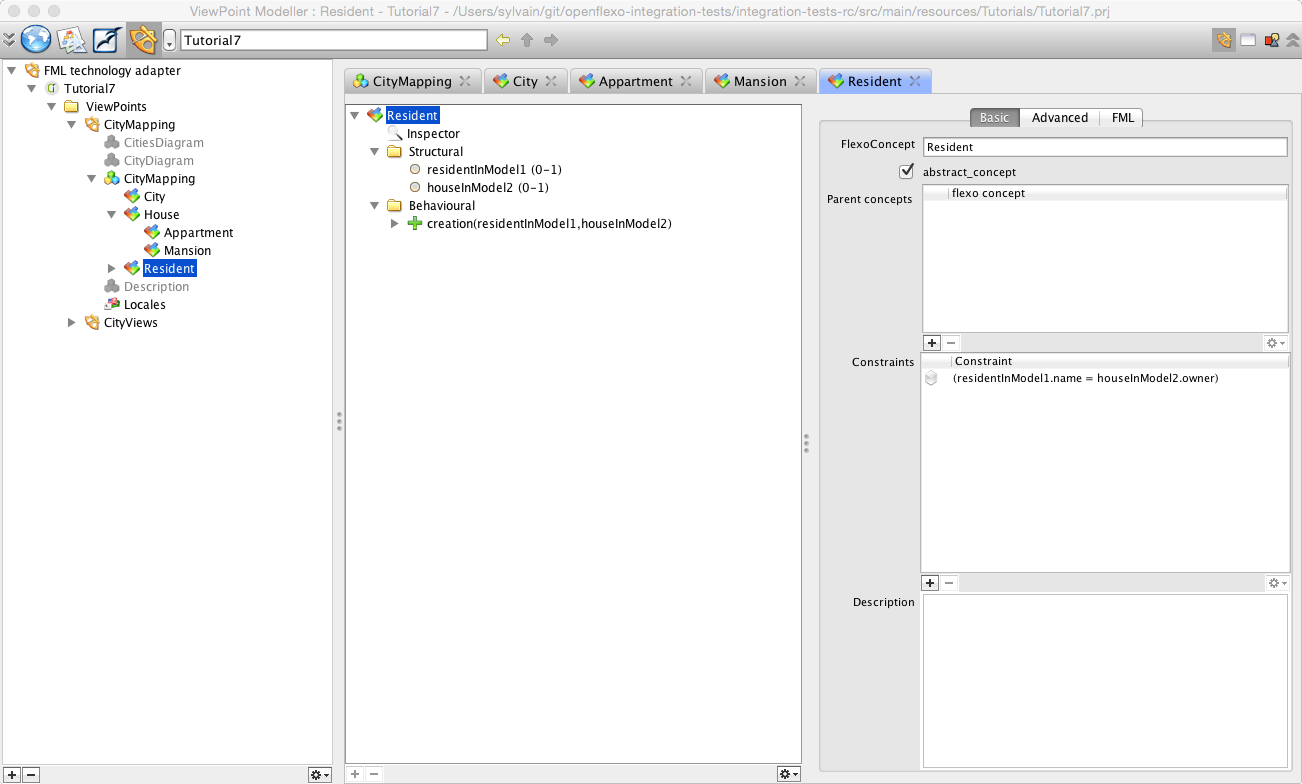
In metamodel1, one instance of Resident class maps the property value owner of one instance of House in metamodel2 (ClassProperty mapping). We have decided here to reference an instance of Resident class in model1, and an instance of House class in model2. To conceptualize this, we then have defined a FlexoConcept Resident, with 2 flexo roles:
- residentInModel1: references an instance of House class in metamodel city1
- houseInModel2: references an instance of House class in metamodel city2
We also need to define following constraint:residentInModel1.name = houseInModel2.owner
4.2.7 Synchronization procedure definition
We now have to define the synchronization procedure for the virtual model be available to synchronize itself with input models. The virtual model has here the responsability of managing the life cycle of all instances (City, House/Appartment/Mansion and Resident). To do so, we need to switch back to virtual model CityMapping. Then select “Behavioural” tab in view representing CityMapping virtual model and double-click on synchronization() behaviour.
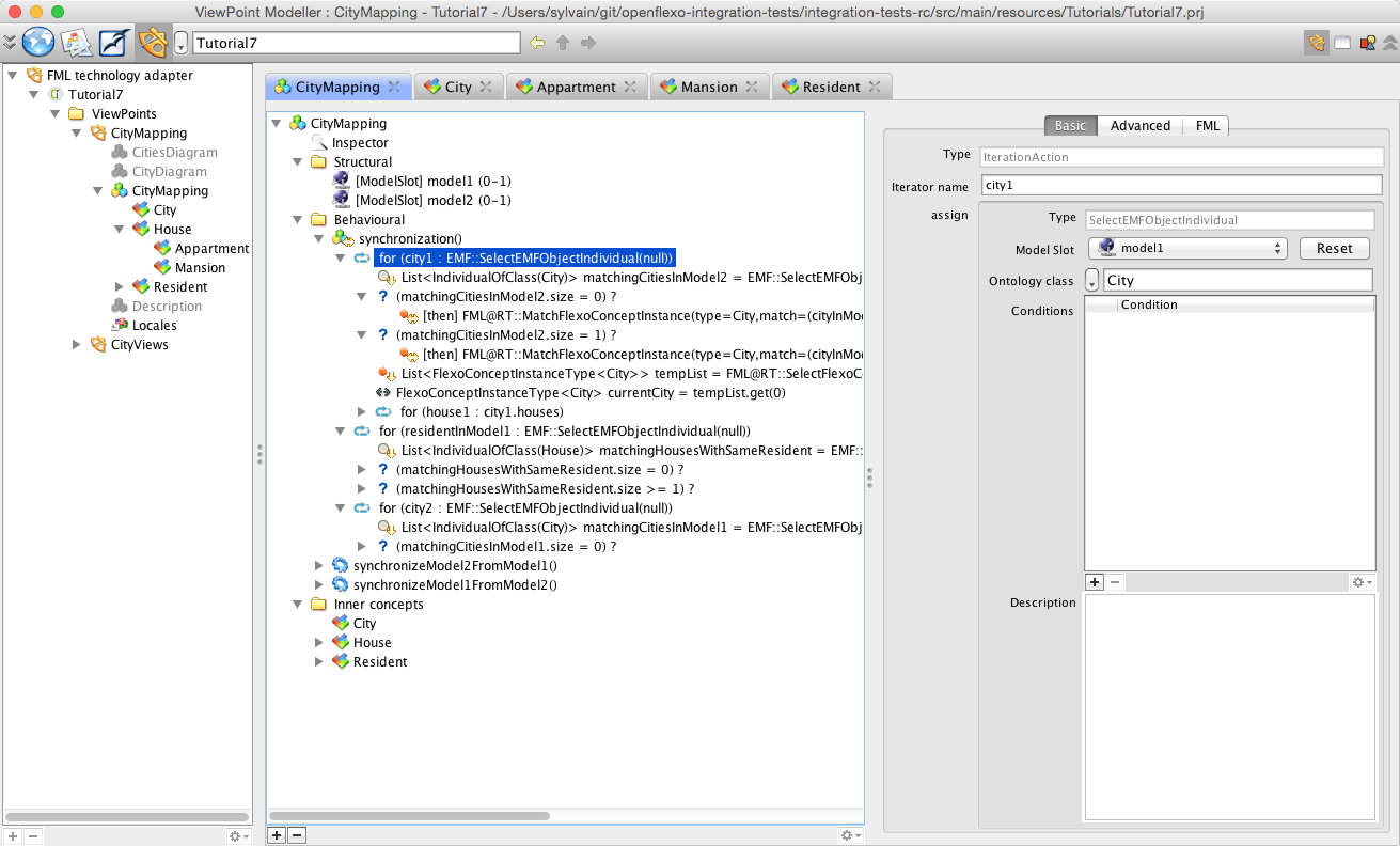
Openflexo defines with the _‘Flexo Modelling Language_’ (FML) a language allowing to program a control graph of actions to be executed as any behavioural feature. The synchronization is one of available behavioural features. Note that actions executed during a control graph are composed with edition action been executed in original technical spaces (through the notion of technology adapters): we read/request/edit the model in their original location with their own technology (here EMF). We see here how to iterate and browse inside the two input models, to find and automatically instanciate mappings (here some instance of FlexoConcepts).
5. Instanciate an example
We will see now how we can use this tooling. Let’s try to execute this with two example models. Lets choose those two models:
- my.model1 located in Model/city1/
- first.model2 located in Model/city2/
First open the ViewEditor module. This module is a generic Run-Time engine for Openflexo FML.
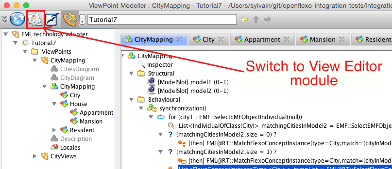
The ViewEditor Module is the module (the modelling workshop) where users instantiate (use) the viewpoints defined in the ViewPoint Modeller (the meta modelling workshop). It’s in this module where a user will use the CityMapping ViewPoint.
Select Tutorial7 project, right-click and select New > Create view
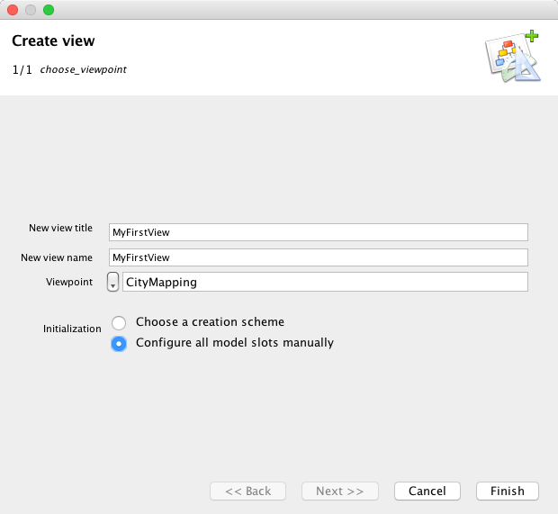
Enter a name and a title for the new View (instance of ViewPoint), and select CityMapping as ViewPoint.
Now, we have to instantiate the mapping VirtualModel. To do so, right-click on the newly created View MyFirstView and select New > Instantiate new VirtualModelInstance
Enter a name and a title for the new VirtualModelInstance. Choose CityMapping VirtualModel.
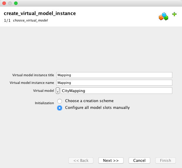
Then click “Next”.
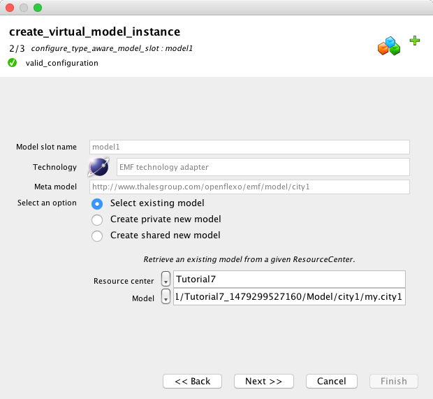
We must connect now the first model slot, which is a model conform to city1 metamodel. We can either select an existing model, or create a new one, deciding to share it or not. We choose here to select existing model my.model1 (look in Model repository you installed at the beginning of this tutorial). Then click “Next”
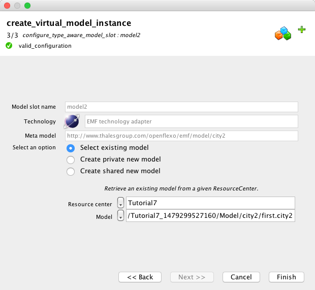
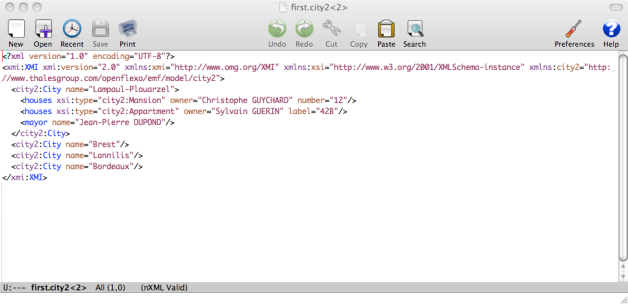
We must connect now the second model slot, which is a model conform to city2 metamodel. We can either select an existing model, or create a new one, deciding to share it or not. We choose here to select existing model first.model2 (look in Model repository you installed at the beginning of this tutorial). Then click “Finish”
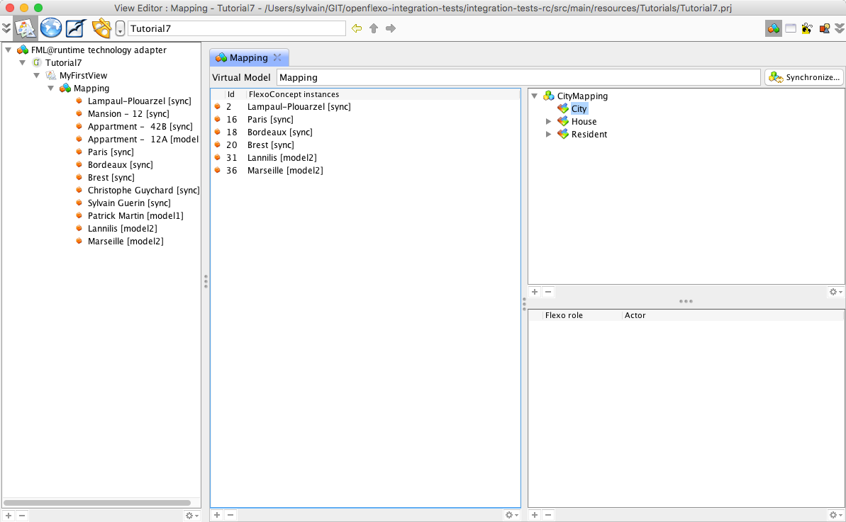
The Virtual Model is now instantiated. As a synchronization scheme is defined on it, the synchronization has automatically been performed browsing input models. Double-click on the newly created MyMapping virtual model instance. Select the City FlexoConcept All mapped cities are now visible as a list of 5 cities. Select Lampaul-Plouarzel
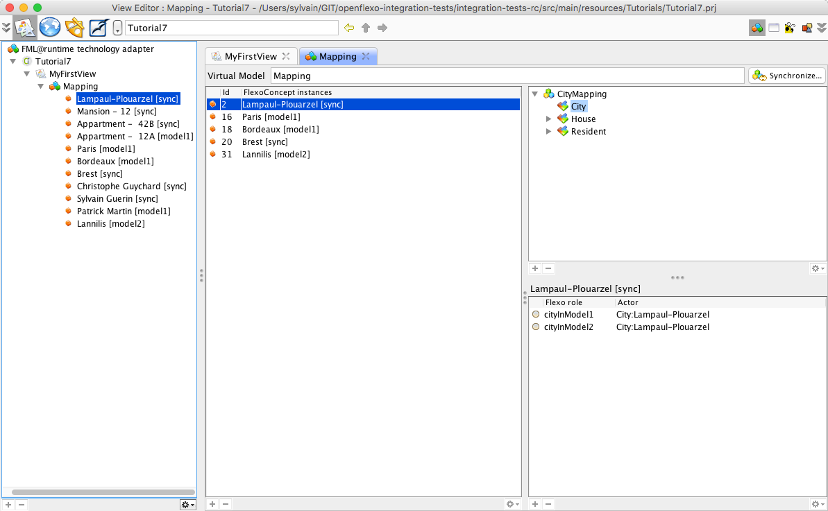
Brest and Lampaul-Plouarzel have been found in both models, and are bound in a City FlexoConcept instance (sync) While selecting Lampaul-Plouarzel, we see that flexo roles cityInModel1 and cityInModel2 are both referencing instances of corresponding cities in input models. Ploumoguer, Bordeaux and Paris have been found in model1 only (my.city1) (model1). Lannilis has been found in model2 only (first.city2) (model2). Now select House flexo concept. The list of all houses is displayed in left table, showing 3 houses. Select Appartment 42B
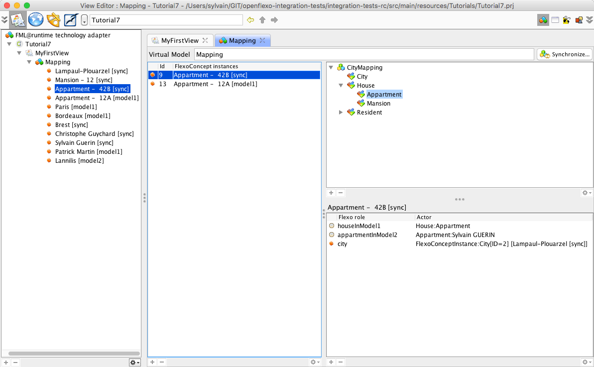
We see that flexo roles houseInModel1 and appartmentInModel2 are both referencing instances of corresponding instances in input models, and city flexo role is pointing to the container’s city (Lampaul-Plouarzel).
6. Operationalize the synchronization
6.1 Defining low-level synchronization/generation actions
Suppose that we want to synchronize the models, considering that a model is the master while the other one is the slave. For example, suppose that we want to generate ‘Bordeaux’ city in model2 (actually only present in model1). Openflexo Modelling Language offers support for defining such behavioural features. Switch back to ViewPoint Modeller module, and open City FlexoConcept. We have defined for this FlexoConcept an action scheme (behavioural feature of action type) called generateModel2FromModel1. Select it.
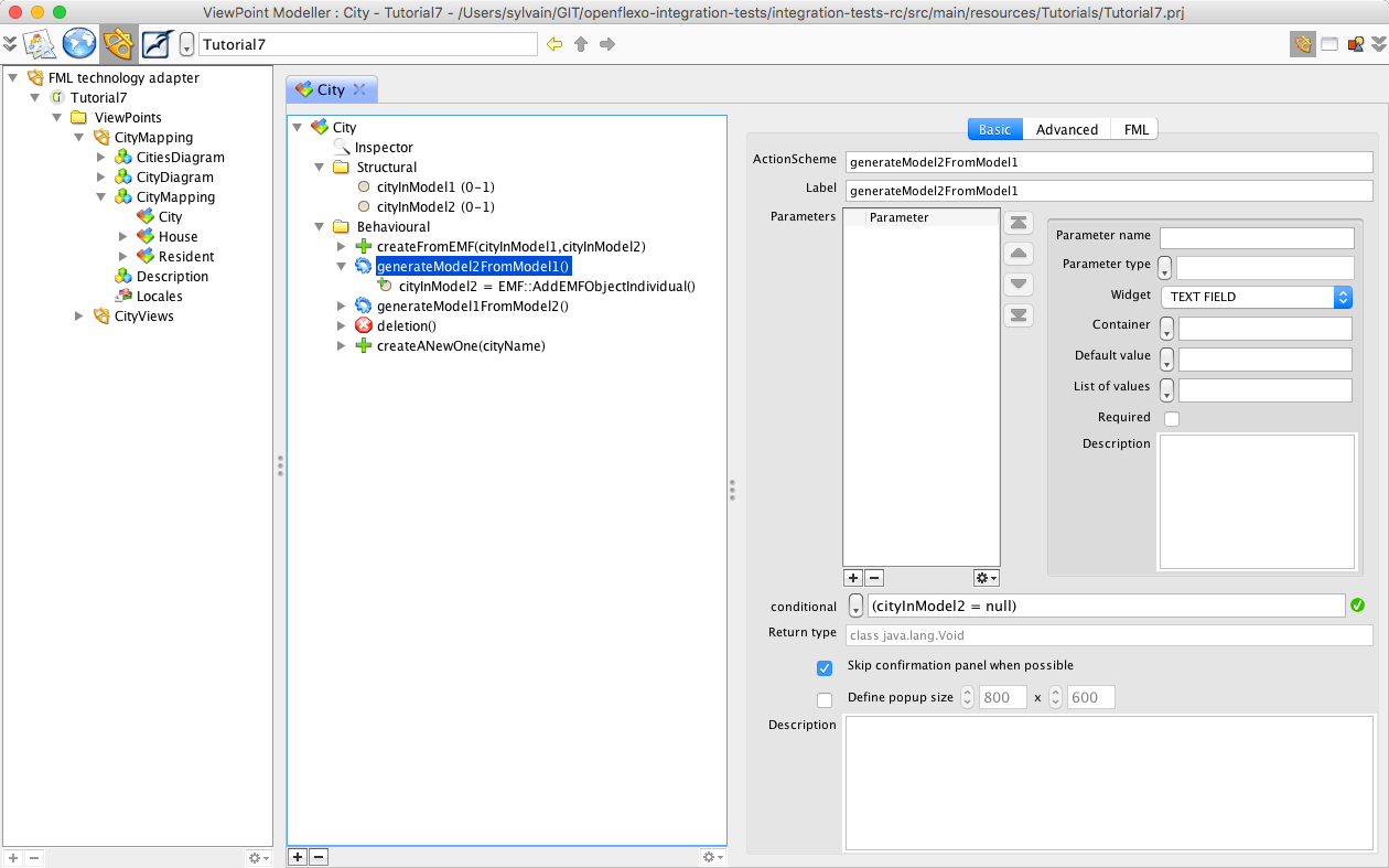
This generation feature is active only if instance of City in metamodel2 is non existant (conditional cityInModel2 = null). A control graph declared in Flexo Modelling Language explicitely defined was to do when this action has been activated. The execution is here trivial and consists of the creation of the corresponding instance in model2, with the name of newly created city set to cityInModel1.name.
6.2 Test generation on a single instance
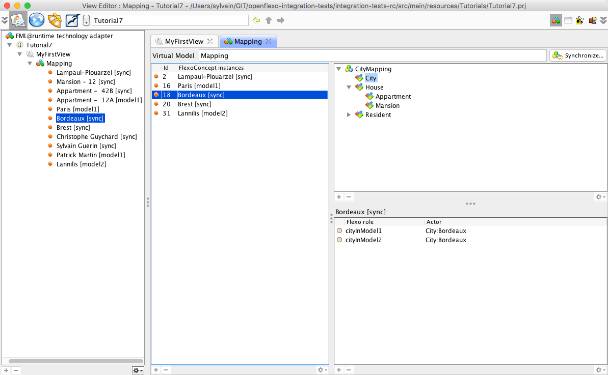
Switch again to ViewEditor module. Select the virtual model instance Bordeaux. Right-click on it, and select generateModel2FromModel1 (this action automatically appears). The flexo role cityInModel2 automatically appears, now referencing in first.city2 model a new instance of City as declared in city2 metamodel. Bordeaux FlexoConcept instance now appears as synchronized sync.
The model first.city2 has really been edited using EMF technology. To state that, select File > Save Project. A popup appears showing all modified resources.
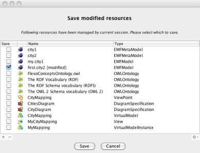
first.city2 EMF model appears as modified. Save it. Open the file first.city2 and see that the file has been modified and that Bordeaux has been added to the model.
6.3 Concurrent modification
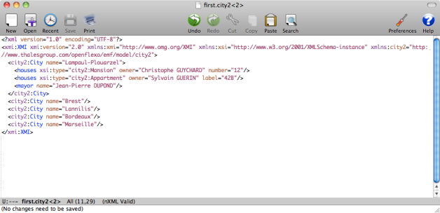
Suppose now that the models are beeing concurrentialy edited (this is the purpose or their being). Edit first.city2 model, and add a City instance (for example a new city called Marseille).
Quit and relaunch Openflexo (dynamic model updating at run-time not supported yet, but this feature should be available soon).
Reopen Virtual Model instance MyMapping.
Click on “Synchronize…”
Marseille city has been automatically instantiated.

6.4 Compose more complex generation actions
If we have 50 000 cities in our models, we probably don’t want to right-click on each instance of the city to generate. The Flexo Modelling Language offers the sufficient expressivity to encapsulate behavioural features in more complex behavioural features. Lets switch again to ViewPointModeller module, and select the CityMapping virtual model. Select “Behavioural” tab and select “SynchronizeModel2FromModel1” action.
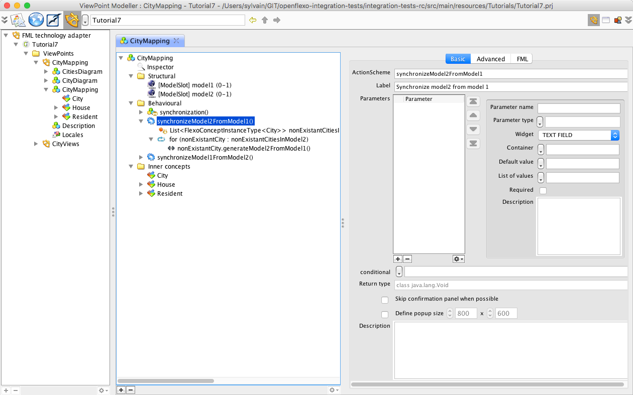
This action scheme (behavioural feature of type action) first invokes a request fetching all instances of City FlexoConcept where the city in model2 is not present (selected.cityInModel2 = null). Note that this request is expressed of the model slot called ‘this’. This is the virtual model instance itself. This shows the utility of the introspective and reflexive nature of the language. Then we iterate on the results of this request, and call for each instance of FlexoConcept City generateModel2FromModel1() action. To test this, switch to ViewEditor module. Select MyMapping virtual model. Right-click and select ‘Synchronize model2 from model1’. All instances of cities only present in model1 are now generated in model2.
7. Building diagram tooling above virtual model
We have seen how we can conceptualy define a ViewPoint handling model mapping issues, and how we can operationalize it. Graphical User Interfaces provided in the context of Virtual Model instances are not user-friendly, and do not suit the requirements for a usable tool regarding to conviviality and ergonomy issues. The idea is to be able to build user-friendly tooling above conceptual layer provided by Virtual Model abstractions. This is what we will show in this tutorial.
7.1 Defining diagrams representing cities
Switch back to the ViewPointModeller module (the “metamodel” editor), and select CityDiagram.
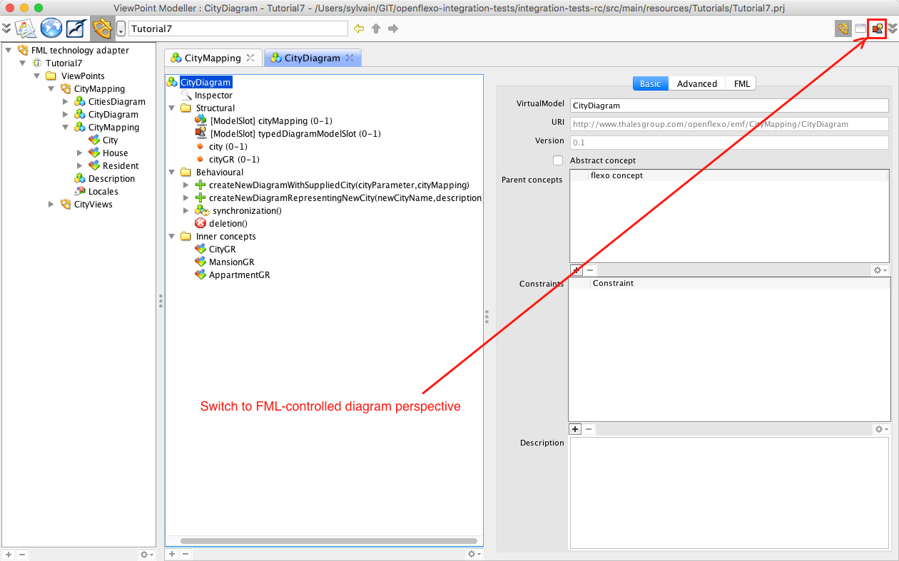
Switch to the FML-controlled diagram perspective. This perspective is offered by the Diagram Technology Adapter to edit an Openflexo’s VirtualModel while interpretating it as a diagram controlled/controlling FML code (what we called a FML-controlled diagram virtual model).
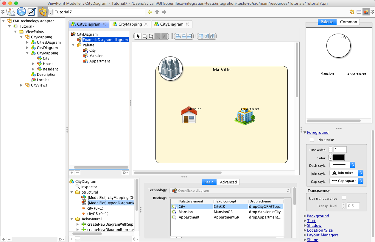
You can browse from here. This is the specification of a diagram-like editor representing part of the model (here a city and its contents). To get more informations on how to build a diagram editor, please consult tutorials 2 and 3.
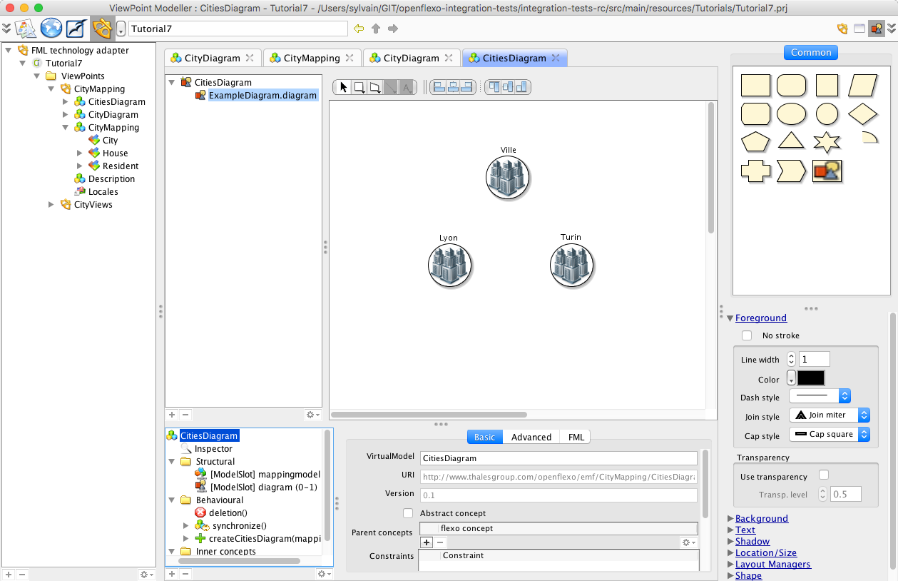
You can also have a look to CitiesDiagramVirtualModel, which present a diagram editor that represent all the cities in a single diagram.
7.2 Experiment CitiesDiagram editor
Let’s experiment this diagram in instances world. Switch back to ViewEditor module.
Select View MyCityMapping.
Right-click and select New > FML-controlled diagram
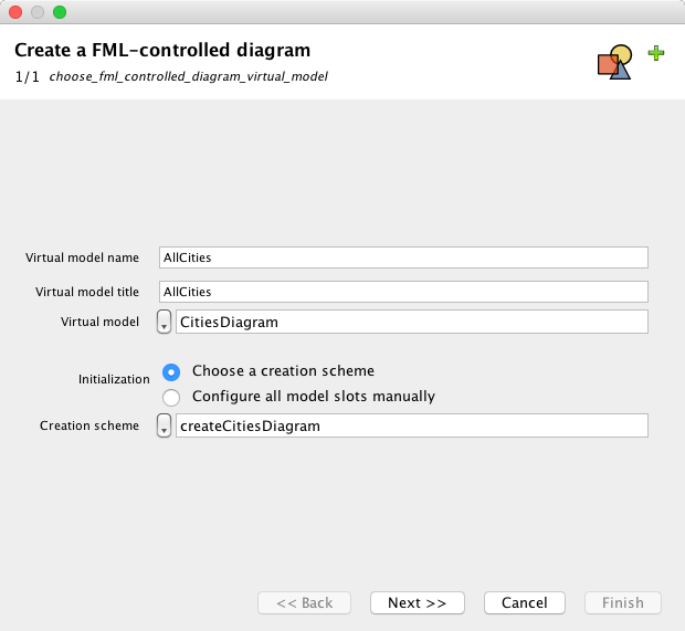
Select type of diagram: CitiesDiagram
Give a name to the diagram: AllCities
And a title: This diagram represents all the cities
Push “Next”
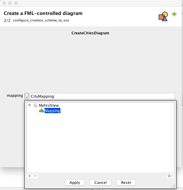
Select “MyMapping” virtual model.
Push “Finish”
We obtain this diagram.
(You need to move all shapes which are all overlapping, since layout features are not developped yet).
Alternatively, select the diagram, and inspect layout manager, select “Balloon layout” for example.
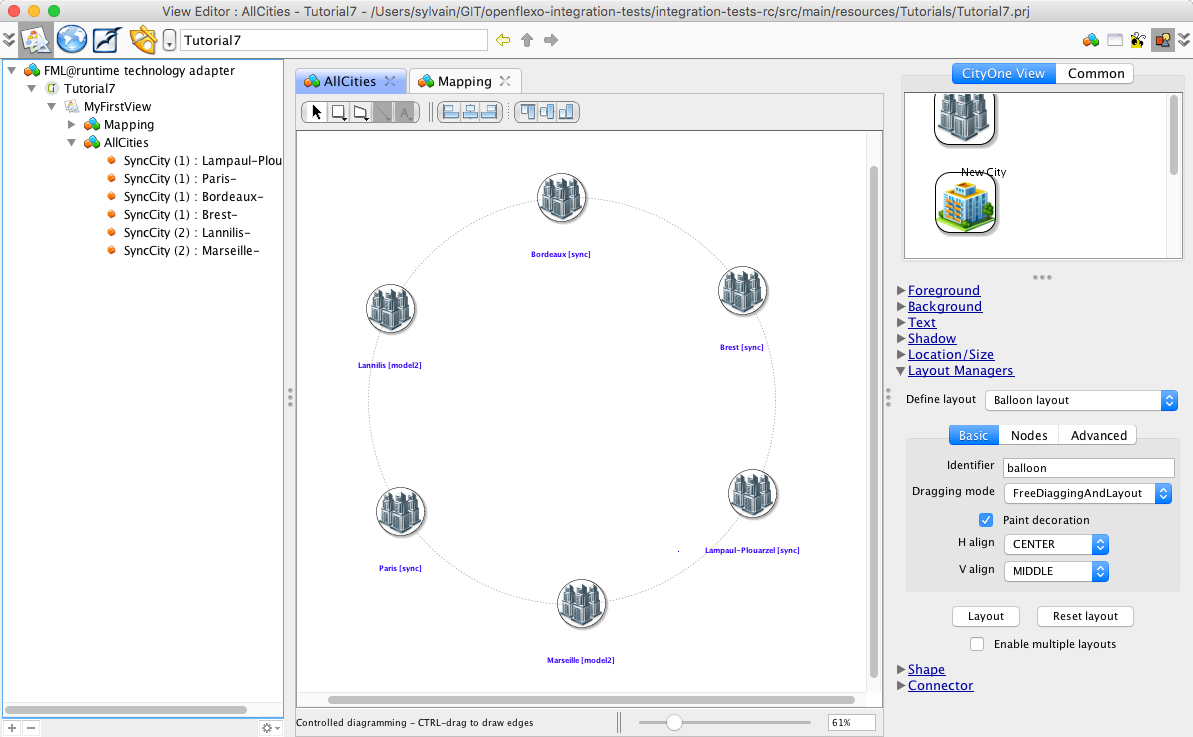
You can arrange this diagram. Save it and reload it.
If you remove a graphical representation, and if you synchronize again the diagram (Right-Click on diagram, then Synchronization), the missing shape will again be added to the diagram.
If models change, for example if new cities are added, then the diagram will automatically be augmented with new graphical representations showing those new elements.
7.3 Experiment CityDiagram editor
Select View MyCityMapping.
Right-click and select New > FML-controlled diagram
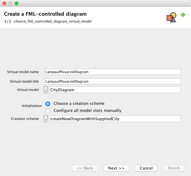
Select type of diagram: CityDiagram
Give a name to the diagram: LampaulPlouarzelDiagram
Push “Next”
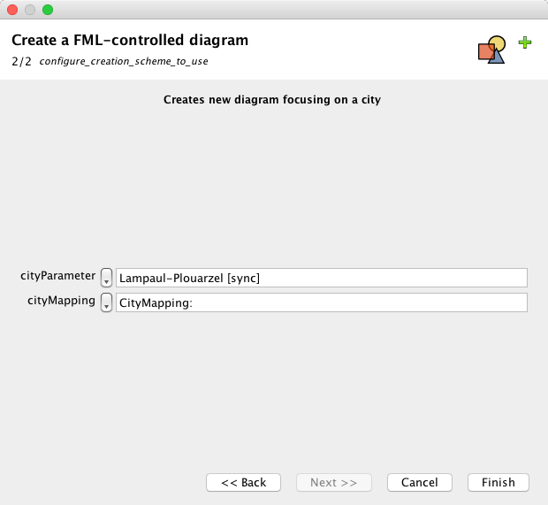
Select “MyMapping” virtual model, and Lampaul-Plouarzel as a city to represent.
Push “Finish”
We obtain this diagram.
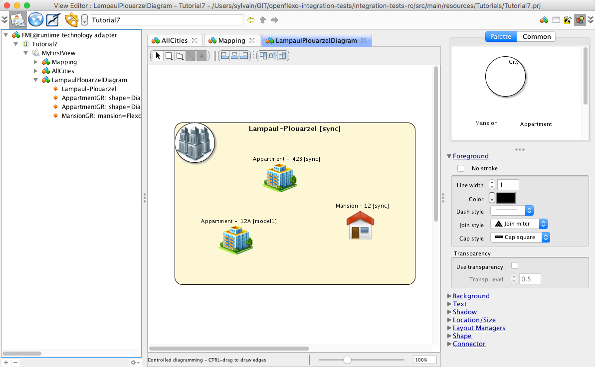
You can arrange this diagram. Save it and reload it.
Same synchronization features than for AllCities diagram applies. Try to remove some shapes, and synchronize again the diagram.